
Home » Utilizing Ultrasonic Technology
Designers of ultrasonic sensors and systems have a range of options when it comes to selecting the frequency, housing design, and mounting solutions using Parsonics’ Transducers. The performance of these transducers can be influenced by factors such as target material, environmental conditions, and the electronics employed. In this overview, we highlight the key considerations when choosing a transducer for your application.
Maximum Sensing Range
Various factors affect the maximum sensing range of a transducer. The specified ranges for Parsonics’ transducers are based on the tone-burst pulse-echo mode and can be found in the “Specifications” section. However, designing an ultrasonic system involves considering more than just the transducer itself. Factors like atmospheric conditions, drive and receive electronics, and signal processing also play crucial roles. Some of these factors are discussed below.
Temperature and Humidity
Changes in temperature affect the speed of sound in the air. Parsonics’ transducers are designed for optimal operation at 22°C. Operating them at significantly higher or lower temperatures can lead to a “detuning” of the acoustic matching layer and a shift in the resonant frequency, resulting in decreased performance. The resonant frequency shifts by approximately -0.8% for every 10°C change. While this reduced sensitivity is acceptable for most applications, wide temperature range applications may require correction. Air characteristics are significantly influenced by environmental conditions. As shown in Figure 1, signal attenuation depends on factors like temperature, humidity, frequency, and air pressure. Humidity has a minor impact on sound speed, with less than a 0.6% change over the temperature range depicted. Parsonics offers internal thermistors for sound speed compensation, and external temperature sensors can provide more accurate calibration over a broader range.
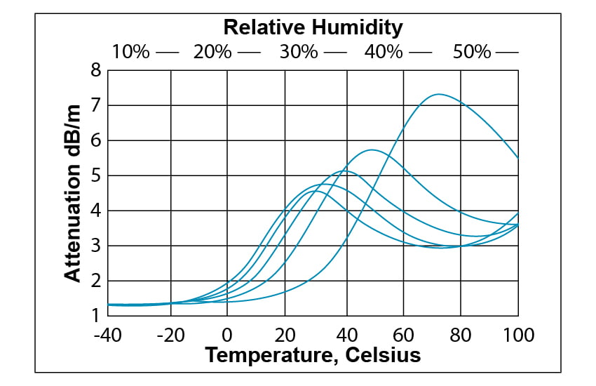
Figure 6: AT Mounting Example
Air Currents and Atmospheric Effects
Maximum measurement ranges can be affected by air turbulence, which can deflect or weaken sound waves, leading to reduced echo signals. Air currents tend to carry sound downwind, and strong currents can deflect sound to the point of missing the intended target. Sudden, significant temperature variations can also affect sound reflection. Light snow or rain in the sound path can attenuate sound waves, reducing the range. Lower frequency transducers emit longer wavelengths, and the impact of snow and rain is less pronounced compared to higher frequencies.
Parsonics’ ultrasonic transducers are resistant to damage from wetting or brief immersion in water. When the sensor is operational, water on the transducer’s surface typically vaporizes.
Interference (Electrical and Acoustical)
Ultrasonic sensors are vulnerable to radio frequency interference (RFI) and electromagnetic interference (EMI). They come equipped with standard internal shielding, and additional shielding may be necessary in certain environments. Shielded cabling options are also available. High-pressure air nozzles, such as blow-off guns, can generate substantial ultrasonic noise that is challenging to filter out, so it’s advisable to avoid installations near these devices. Transducers mounted on vibrating equipment can experience mechanically coupled interference. To mitigate vibration transmission to the transducer, consider using a compliant mounting material.
Beam Angle
Transducers emit energy in a specific beam pattern. The main lobe contains the majority of the energy and defines the beam’s width. Energy outside the main lobe is concentrated in sidelobes, which can create phantom echoes and obscure the actual target location. While no transducer is entirely free of sidelobes, Parsonics designs its transducers to have low sidelobes, typically at least 17 dB below the main lobe. Beam width is specified at the -3 dB level in the full-angle beam pattern, with the beam angle for each model detailed in our catalog specifications. Wider beam angles reduce the transducer’s sensing range and offer less target discrimination compared to narrower beam models. Wider beams disperse acoustic energy over a larger area, resulting in fewer echoes from potential targets than with narrower, more concentrated beams. In the case of narrow beam angles, variations in echo amplitude are more significant, particularly with irregular surfaces.
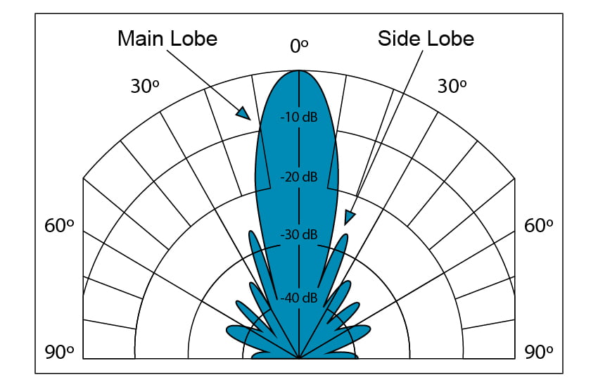
Figure 3: Typical Beam Pattern
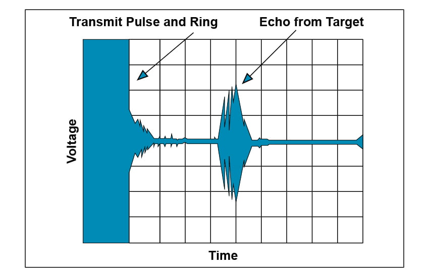
Figure 4: Transmit Ring Example
Minimum Sensing Range
The type of electrical pulse used to drive the sensor significantly affects the level of ringing. Parsonics characterizes ringing time based on a tone burst drive, typically involving ten cycles at the optimal operating frequency. Transducers have various vibration modes, some strongly coupled to air and others not. The objective when designing a system is to drive the transducer at a frequency strongly coupled to air, avoiding the excitation of extraneous resonances. The use of a tone burst (narrow bandwidth) is beneficial, whereas a wide-band transmit scheme can excite undesirable vibration modes. For example, “impulse” drive electronics, applying a high-voltage, short-duration burst of energy, can excite virtually all vibration modes, including undesirable ones that dissipate their energy more slowly, leading to increased ringing.
All air transducers have a secondary resonance near the desired resonance frequency, a result of using an acoustic matching layer to better couple the piezoelectric ceramic element to air. See Figure 5. This secondary resonance is less strongly coupled to air and exhibits more pronounced ringing than the desired resonance.
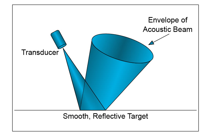
Figure 5: Transmit Response Showing Adjacent Responses
Mounting
Because the transducer is an electromechanical device, it can transmit vibrational energy to the transducer housing. A rigid mount can amplify these vibrations and increase ringing. A compliant mount has the least effect on sensor performance. Transducers should not be forcibly press-fit into a mounting location. If a rigid mount is necessary, it’s advisable to glue the sensor into a slip-fit hole, ideally contacting only the front or rear edges of the transducer. For mounting in a pocket, use a soft encapsulant.